Pneumatic System Shock Absorption: A Guide to Hydraulic Buffer Function, Design & Selection
What Does a Hydraulic Buffer Do?
Hydraulic buffers are precision-engineered components designed to absorb kinetic energy and reduce the impact of moving parts in machinery. Their purpose is to slow down and stop motion safely, avoiding mechanical damage and reducing noise, shock, and wear.
You’ll find them in:
- Factory automation systems
- Conveyor systems and transfer lines
- Pneumatic actuators and robotic arms
- Elevators, lifts, and safety barriers
Definition and Function
A hydraulic buffer transforms motion into heat through controlled hydraulic resistance. When an object in motion pushes against the buffer, hydraulic fluid is forced through restricted channels, converting the object’s kinetic energy into heat, which dissipates harmlessly.
This controlled deceleration improves machine stability, repeatability, and safety—making hydraulic buffers indispensable in automated environments that demand precision and protection.
The Difference Between a Hydraulic Buffer and a Standard Buffer
Here’s how hydraulic buffers stand apart from traditional mechanical buffers:
| Feature | Mechanical Buffer (e.g., spring) | Hydraulic Buffer |
| Energy absorption method | Spring compression | Hydraulic fluid throttling |
| Deceleration control | Often abrupt and inconsistent | Smooth, adjustable, and controlled |
| Noise level | Can be loud | Quiet, vibration-dampening |
| Rebound behavior | Unpredictable bounce | Predictable, no bounce |
| Suitability | Low-speed/light-load systems | High-speed/heavy-load applications |
In practice, hydraulic buffers enable safer operation and longer component life, particularly in systems requiring frequent, high-speed motion.
Design and Construction
Understanding a buffer’s internal design reveals why it outperforms mechanical alternatives.
Key Components and Their Roles
Let’s break down the core components:
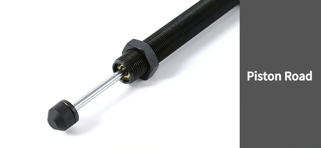
- Piston Rod: Connects to the moving part and transfers force into the buffer.
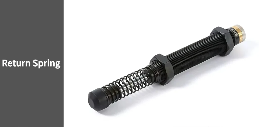
- Return Spring: Drives the piston back to its starting point once compressive force is released.
- Hydraulic Fluid: The medium that absorbs and dissipates impact energy.
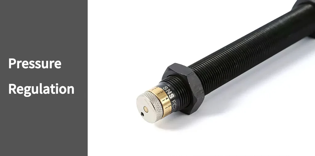
- Throttle Mechanism: Precisely controls fluid flow to achieve smooth deceleration.
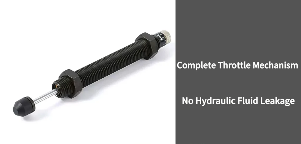
This configuration ensures that each impact is absorbed efficiently and predictably—crucial in automated systems where downtime is costly.
Variations in Design (Fixed vs Adjustable Types)
Hydraulic buffers come in two primary designs:
- Fixed-Type Buffers
- Have a preset damping force
- Lower cost and simple to install
- Ideal for systems with consistent load and speed profiles
- Have a preset damping force
- Adjustable-Type Buffers
- Allow manual tuning of damping force
- Accommodate changing conditions and test setups
- Well-suited for R&D, prototyping, or dynamic production lines
- Allow manual tuning of damping force
For a practical look at product variations, explore the hydraulic buffer section at SNS Pneumatic, which features both types across a range of sizes and configurations.
Working Principle
Let’s walk through what happens inside a hydraulic buffer during operation.
Energy Conversion Process
When a moving object strikes the buffer:
- The piston rod compresses into the cylinder.
- Hydraulic fluid is forced through precisely machined throttle holes.
- Resistance is created, converting kinetic energy into heat.
- Cooling is achieved by heat dissipation through the cylinder wall or designed cooling provisions.
This process offers controlled deceleration without rebound, which is essential in high-precision automation.
Throttling Mechanism and Reset Function
Functionally, the buffer relies primarily on its throttling valve system:
- Fluid flow is restricted through fixed or adjustable orifices.
- This controls the rate at which energy is dissipated.
- Adjustable models offer fine-tuning to match application requirements.
Upon dissipation of the kinetic energy, an internal spring mechanism retracts the piston rod. This reset is automatic and fast, enabling high-cycle-rate usage.
Buffer Distance and Design Parameter Relationships
Buffer stroke (i.e., piston travel length) plays a major role in energy handling:
- Shorter strokes: Faster response, but lower energy capacity
- Longer strokes: Higher energy absorption, more space needed
Other influential design parameters:
- Piston diameter affects force resistance.
- Throttle size determines deceleration rate.
- Oil volume and viscosity influence energy transfer and temperature stability.
Matching these specs to your application ensures longer buffer life, quieter operation, and fewer failures.
How to Use a Pneumatic Hydraulic Buffer Properly?
Installing a hydraulic buffer is only half the job. Proper selection and application are key to getting the most value.
Factors Affecting Model Selection
Choosing the wrong buffer can lead to equipment damage or early failure. Always consider:
- Moving mass (kg)
- Impact velocity (m/s)
- Cycle frequency (how often impacts occur)
- Mounting position and alignment
- Ambient temperature (viscosity changes can affect performance)
Also consider built-in safety margins. A buffer rated for 150% of your system’s typical impact load will last longer and maintain performance under stress.
Steps and Formulas for Choosing the Right Buffer
A methodical approach simplifies the selection process:
- Calculate Impact Energy

- m = moving mass (kg)
- v = velocity at impact (m/s)
- Match Buffer Capacity
- Compare your result with the maximum energy absorption capacity of available buffer models.
- Compare your result with the maximum energy absorption capacity of available buffer models.
- Verify Stroke Requirements
- Ensure you have enough space for the full buffer stroke, including any mounting brackets or fixtures.
- Ensure you have enough space for the full buffer stroke, including any mounting brackets or fixtures.
- Check Compatibility and Environment
- Double-check mounting orientation, stroke direction, and exposure to dust or moisture.
- Double-check mounting orientation, stroke direction, and exposure to dust or moisture.
Manufacturers like SNS Pneumatic provide detailed specs and support to help with proper sizing and setup.