Solenoid Valve Connectors: A Comprehensive Guide
Solenoid valve connectors are essential components used to electrically connect solenoid valves to their power sources in various industrial and commercial applications. They not only ensure secure connections but also facilitate easy maintenance and troubleshooting of valve systems.
Understanding the right connectors for your solenoid valves is crucial for system reliability and performance. Continue reading to discover the types, designs, and specifications that will optimize your setups for peak efficiency and safety.

What is Solenoid Valve Connector?
A solenoid valve connector is a standardized interface used to link the electrical coil of a solenoid valve to the power supply and control circuitry. This connector is crucial in ensuring reliable electrical connections that can withstand various environmental conditions without compromising the operation of the valve. It simplifies installation, maintenance, and replacement by offering a plug-and-play solution that minimizes wiring errors and reduces downtime. Employed widely across many industries, these connectors come in different shapes, sizes, and specifications to accommodate diverse requirements and applications.
How is Solenoid Valve Connected?
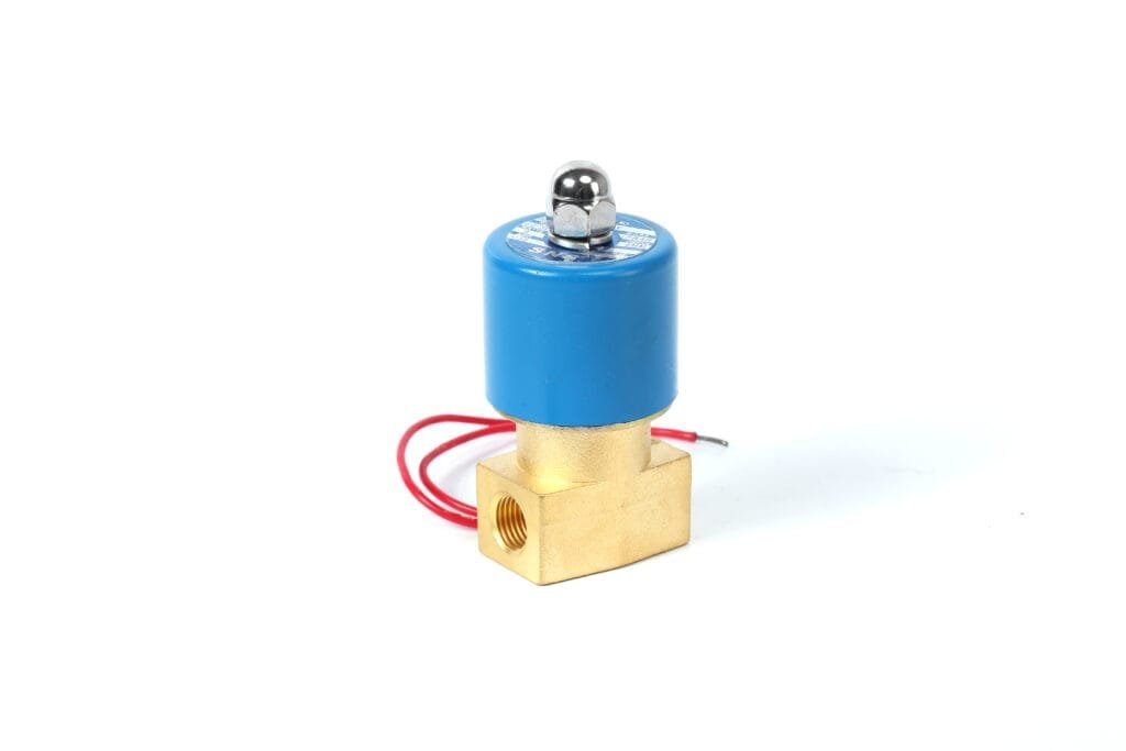
Initially, the valve body must be installed into the piping system following manufacturer instructions to allow for correct flow direction and secure attachment. The solenoid coil, which is the actuating element, is then placed onto the valve body.
The electrical connection of a solenoid valve involves its solenoid coil being wired to a power source. This process typically requires attaching wires from a solenoid valve connector to corresponding control circuit terminals or directly to an interface box if integrated wiring solutions are employed. It’s critical during this stage to adhere strictly to electrical codes and standards while also confirming correct voltage and polarity alignment.
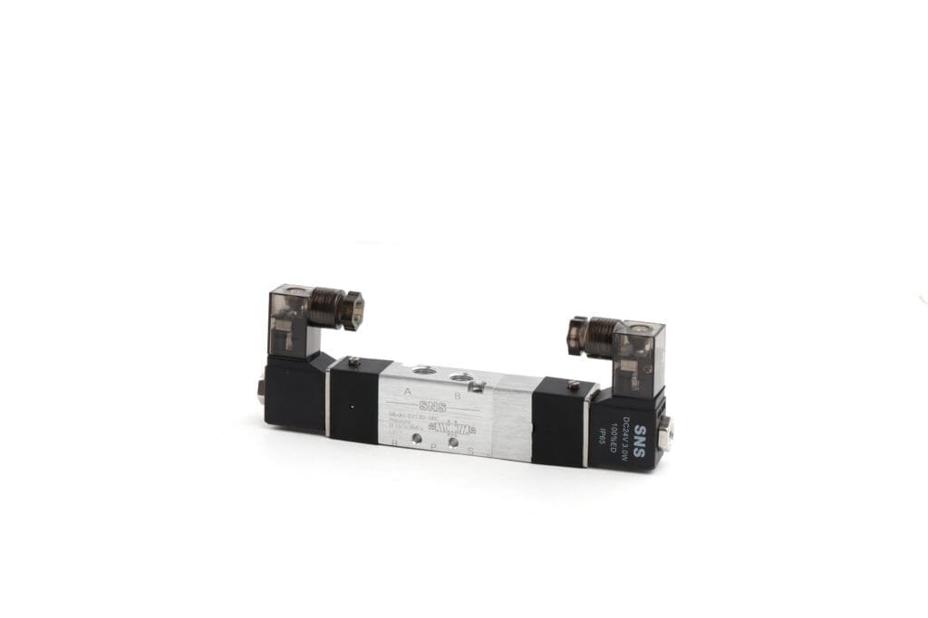
To facilitate the secure transmission of electricity and signals, solenoid connectors are mounted on top of the solenoid coil using a designated locking mechanism such as screws or locking clips. Ensuring a tight and corrosion-free electrical connection between the coil and its power source is paramount for reliable operation.
Lastly, after establishing both mechanical installation and electrical connections, it’s important to test the operation of the valve by applying power briefly to confirm that electromagnetic actuation occurs without leaks or malfunctions.
| Step | Description |
|---|---|
| Installation of Valve Body | Attach valve body securely into piping with correct flow direction. |
| Placement of Solenoid Coil | Position solenoid coil on top of prepared valve body. |
| Wiring Electrical Connections | Wire solenoid coil to power source conforming with standards; verify voltage and polarity. |
| Mounting Solenoid Connector | Use appropriate locking mechanism to attach connector to solenoid coil. |
| Testing Operation | Apply brief power surge to test functionality; check for leaks or mechanical failures. |
Solenoid Valve Connector Types
Solenoid valve connectors are crucial components used to connect the solenoid coil to the electrical power source. Three common types of connectors are recognized in the industry: type A, type B, and type C. These types vary in their design, size, and characteristics which suit differing operational requirements and installation conditions.
Below is a detailed table summarizing key attributes of each solenoid valve connector type:
| Feature | Type A Connector | Type B Connector | Type C Connector |
|---|---|---|---|
| Shape | Rectangular | Low-profile rectangular | Euro-style cylindrical |
| Pin Spacing | 18mm | 11mm | 8mm |
| Indicators | Often includes LED | May include LED | Less common |
| Voltage Spike Protection | Commonly includes suppression diodes | Some models include suppression diodes | Varies by model |
| IP Rating | Usually IP65 | Usually IP65 | Usually IP65 |
| Installation Flexibility | Good | Better | Best due to round cable entry |
| Design Suitability | Varied industrial applications | Space-constrained environments | Tight spaces or complex machinery |

Solenoid Valve Connectors with Circuit Functions
Solenoid valve connectors equipped with circuit functions extend beyond simple electrical connections. They serve a dual purpose: establishing a secure and reliable connection between the solenoid and its power source, while simultaneously integrating protection and management features for enhanced performance and longevity.
| Feature | Function | Benefit |
|---|---|---|
| LED Indicator | Visual indication of power status | Facilitates easy diagnosis |
| Freewheeling Diode | Voltage spike suppression at de-energization | Protects against electronic component damage |
| Rectifier | Converts AC to suitable DC | Allows AC-powered systems to use DC-operated solenoids |
| Varistor | Resistance variation with applied voltage | Guards against transient voltage spikes |
Solenoid Valve Connector with LED
Solenoid valve connectors that come equipped with Light Emitting Diodes (LEDs) provide real-time visual indication of their operational status. When the solenoid valve is activated, the integrated LED illuminates, signifying that power is reaching the valve, which helps in troubleshooting and ensures that system operators can easily verify functionality. These LEDs are particularly useful in environments where noise can obscure audible clicks from the valve or in circumstances where access to measure voltage might be difficult. The presence of an LED on a solenoid connector also adds safety by reducing the need for direct electrical testing.
Pole Protection and Freewheeling Diode
When a solenoid is de-energized, the collapsing magnetic field generates a voltage spike known as back electromotive force (EMF). This can be harmful to solid-state switchgear or sensitive components within a control system. A freewheeling diode, also referred to as a flyback diode, is connected across the solenoid coil terminals in such orientation that it is reverse-biased during normal operation and does not affect the current flow.
Once the power is cut off and the magnetic field begins to collapse, the diode becomes forward-biased, allowing current generated by this collapse to circulate through the coil and the diode rather than through other components in the circuit. By doing so, it effectively clamps down on high-voltage spikes, offering pole protection against electrical transients. This component is indispensable for preventing inadvertent damage to electronic controls and prolonging service life of both the valve and its control gear.

Rectifier
This component consists of diodes arranged in specific configurations depending on whether a half-wave or full-wave rectification is desired. A half-wave rectifier uses one diode and effectively removes one half of the alternating waveform, while a full-wave rectifier utilizes four diodes in a bridge configuration to invert the negative half of the AC waveform, producing a smoother DC voltage output.
The inclusion of a rectifier can also be beneficial for reducing electromagnetic interference (EMI) since it limits abrupt changes in current that can generate noise. Additionally, circuits with rectifiers tend to have improved efficiency and reduced thermal stress on components because they deliver consistent voltage and current levels suitable for the solenoid’s optimal operation.
When selecting connectors with integrated rectifiers, it’s imperative that users match their electrical requirements to prevent overvoltage situations that could compromise device functionality and lifespan.
Varistor
A varistor is a type of resistor with a non-ohmic current-voltage characteristic that is typically used to protect circuits against excessive transient voltages. When it comes to solenoid valve connectors, incorporating a varistor can be essential for safeguarding the control circuit from voltage spikes that occur during the switching process. The varistor functions by clamping transient voltages to an acceptable level; when the voltage exceeds a certain threshold, the resistance of the varistor drops dramatically, diverting the excess energy and thus preventing it from damaging sensitive electronic components.
Varistors are particularly useful in environments where high voltage surges are likely or where highly robust operational reliability is required. It’s essential that users select a varistor with appropriate voltage ratings to match the specific requirements of their solenoid valve system. Not only does this component offer protection against sudden surges, but it can also help in prolonging the lifespan of both the solenoid valve and its connector by mitigating wear from constant electrical stress.
Selection Criteria for Solenoid Valve Connectors
When selecting a solenoid valve connector, various criteria must be considered to ensure compatibility and performance within the application.
| Criterion | Description |
|---|---|
| Electrical Requirements | Voltage and amperage specifications the connector is designed to handle. |
| Environment | Operating conditions including temperature range, moisture exposure, chemical resistance, and mechanical endurance required of the connector. |
| Current | Maximum electrical current capacity of the solenoid valve connector before risking damage or failure. |
| Size and Dimensions | Physical size considerations for compatibility with solenoid valves as well as spatial constraints in application settings. |
| Thread Types | The specific type of threading used on connectors that must align with valve or system interfaces for a secure connection. |

Electrical Requirements
When assessing the electrical requirements for solenoid valve connectors, several factors are critically evaluated to ensure compatibility and optimal performance.
The voltage rating is paramount; it has to match the solenoid’s operating voltage which typically ranges from 12V DC to 240V AC in industrial applications. The choice between alternating current (AC) and direct current (DC) connectors also hinges upon the type of solenoid valve being used.
Additionally, the power consumption of the solenoid coil must be considered. This involves looking at both the inrush and holding power requirements. Inrush power is higher as it is needed to initially activate the solenoid, whereas holding power—generally lower—is required to maintain its state.
Frequency is another essential parameter, especially for AC solenoids, as different regions operate on different electrical grid frequencies usually either at 50 Hz or 60 Hz.
Ensuring that the rated current of the connector aligns with that of the valve prevents overheating and potential equipment failure. Exceeding a connector’s specified amperage can lead to dangerous malfunctions.
Moreover, checking insulation standards such as IP ratings guarantee that connectors can withstand certain levels of moisture and particulate exposure without performance degradation.
Environment
When assessing the environmental impact on solenoid valve connectors, it is imperative to consider various factors that may influence their performance and longevity. The connector’s ability to withstand different temperatures, both operational and during storage, plays a critical role. High or low extremes of temperature can affect the material properties. Moisture levels are also crucial; connectors may need to be waterproof or at least resistant to high humidity conditions.
Chemical resistance is another consideration, especially in industrial settings where exposure to aggressive substances might occur. Dust and particulate matter could interfere with electrical connections if ingress protection isn’t adequate. IP ratings indicate the level of sealing effectiveness against foreign objects such as dust and water. Physical impacts and vibration are additional environmental variables that require attention as they can lead to wear or disconnection over time.
Current
The connector must safely conduct the electrical current required to activate the solenoid without overheating or suffering damage. Current ratings are typically specified in amperes (A), and it’s imperative to ensure that the chosen connector can handle the peak current drawn by the valve during operation, as well as continuous current levels.
As part of a robust design criterion, it is also important to consider potential surges in the system which may briefly exceed normal operating current. Connectors are sometimes rated with both a nominal (normal) current and a maximum interrupting current, which they can withstand for a short period without failure.
Using a connector that cannot accommodate sufficient current can result in excessive heat generation, leading to insulation breakdown and potentially creating a fire hazard or causing complete device failure.

Size and Dimensions
The dimensional criteria include the length, width, height of the connectors, as well as specific dimensions relating to the fitting such as the pitch of any mounting holes. It’s imperative that these measurements align with those of the corresponding solenoid valve to facilitate a secure and leak-proof connection.
The industry has standardized several form factors for size and dimensions that fit most solenoid valves. However, custom sizes are sometimes necessary for special applications. Exact sizing is also essential for maintaining proper clearances within a system to prevent interference with other components.
Manufacturers usually provide detailed drawings or CAD models that specify all relevant dimensions to help buyers in selecting the correct connector. When physical space is constrained in an application or there is limited room for wiring, compact or miniature connectors may be required. Recognizing thread types on both the solenoid valve and connector is equally important—they must match (e.g., NPT, BSP) to ensure a tight seal and proper assembly.
Thread Types
Thread types refer to the detailed profiles of threads on the connector components that screw together, ensuring a secure fit between the connector and the valve.
The commonly used thread types for solenoid valve connectors include metric threads, National Pipe Taper (NPT) threads, and Gas (G) or British Standard Pipe (BSP) threads. Metric threads are measured in millimeters and are widely utilized worldwide due to their standardized sizing. NPT threads are a U.S.-standard taper thread mainly used for pipes carrying fluids at high pressure. They create a tight seal by mating with complementary thread angles and diameters. G or BSP threads can be either parallel or tapered and are commonly found in applications across Europe and Asia; they have been traditionally used for pipes transporting gases or liquids.
It is crucial that the appropriate thread type is selected to match the port of the solenoid valve; mismatches can lead to poor sealing or even damage to both the connector’s housing and the valve’s port.
In conclusion
In conclusion, solenoid valve connectors are crucial components that ensure secure and reliable electrical connections in a variety of industrial and commercial systems, facilitating effective control of fluid flow.
To maintain optimal performance and safety in your applications, it is essential to select the appropriate connector type for your specific needs. Reach out to a specialist or consult with a supplier to find the ideal solenoid valve connector that matches both your technical requirements and industry standards.


